


|
SETTINGS / TESTS |
|
1 |
Connect the COM port (or IP in case of use of CMH9000PER or a COM/IP converter like FENGNOME), config the COM porto in config.txt file of the software and launch the software. When launched, the software will connect automatically to the machine (or press button connect to made it). Contemporarly to the communication the green LED on FENCEN unit has to blink, otherwise there are problem with serial communication. When it’s all OK, press READ button to download from the analisys unit the actual configuration. |
|
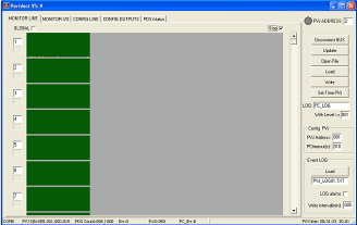
2 |
Verify that the software counts the right number of connected sensors (in monitor line windows will appear many green bars as the read sensors are) and verify that the received signal is regular (bars must be green and continuous, otherwise verify that there are not more sensors with same address). The number of sensors will also appear on the lower part of the software. |
|
3 |
Find the critical sensor for what regards the installation, to made the correct sensors association (for example first and last sensor, 90° degrees angles, ecc) Then, from “config line” window, select CP1 and CP2, the FENSEN10 that will be compared with the analized detector, to decide if the received signal is an alarm or not. |
|
4 |
Make detection tests with the default configuration, to verify all the received pulses, and decide wich ones are considered alarm or not. When the tests are made, the user can press stop on the Monitor Line window. The he can configure, in config line window, the parameters of each analized detector. The parameters are : min-Dmax : They represents the sensivity of the sector to be set (scale 1/120). LOGIC : A) Value insertion. The absolute value 1/120 of the pulse is converted in base of the input values of dmin-dmax. Es) with 30-60 the value 1 will be converted in 30 and the value 120 in 60. B) At the inpulse receiving its value is converted to the new scale. Es) A pulse with value 60 will become 45 (in dmin=30 and dmax=60) C) Comparing with CP1 and CP2. If the pulse difference between the sensors is higher that the value of point B (N.B : in value 1/120), this value will be counted as alarm, otherwise not. Es) CP 1 and CP2 have a value of 10 (in scale 1/120). 60-10>45(point B) —> Alarm 2) Max : Inpulse value, in scale 1/120, where the pulse read is considerate immediately an alarm, ignoring the pulse counter function. A value of 0 disable the function. 3) TimeW—AlarmCnt : Pulse counter, set it means that the output will be changed of status if, in a time window TimeW (seconds : value/2), wll be triggered AlarmCnt alarm pulses. |
|
5 |
Remake the detection tests and restart from point 4 until the finding of the wanted situation. After, in necessary, relate the detectors to the 10/16 outputs, always from menu “Config Line”. |